Headlight Door Motor
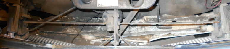
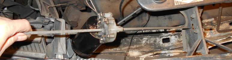
After compressing the clips and sliding them on to the torsion bar, the bar easily popped out of the two door shafts with the aid of a screwdriver. (The round shafts have a slot for the torsion bar.)
This is how motor, with the long torsion bar, is removed and re-
The bar loosely slides through the gearbox.
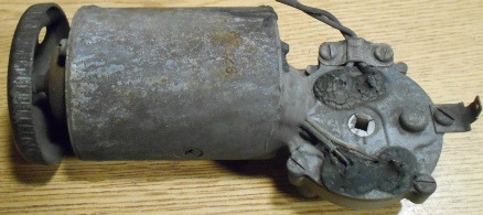
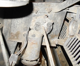
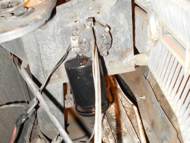
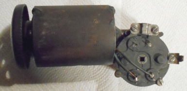
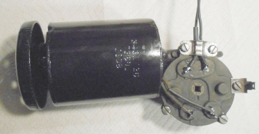
Motor before removal
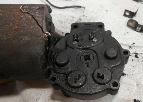
Cleaned and repainted motor re-
I found nothing wrong with the motor/wiring/switc hes, so it must have just needed cleaning
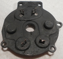
As removed from car and torsion bar slid out. Those black patches around the terminals are some sort of hardened tar which was removed with solvent and a pocket knife.
After cleaning ––>
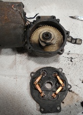
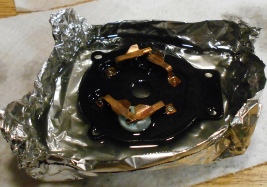
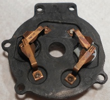
Switch plate removed. Gear has just a little grease, probably so that it would not end up on the switch
Switch plate was soaked in an improvised aluminum foil dish filled with Isopropyl alcohol, then blown dry. The gear and cam was also cleaned up.
A small amount of grease was applied to the worm gear. Unlike the power window motors, only a small amount of grease was used out of fear of getting it on the switches. I would have put dieelectic grease on the switches, but forgot. I also left out a replacement “O” ring by accident.
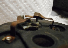
Closeup of one switch. The disc rotates when hit by the cam that sits on top of the gear. The disc has two posts that stick up and push each contact up so that they touch turning the switch on. When the disc is rotated slightly by the cam, one switch arm falls out of contact, stopping the motor rotation in that direction.
After soaking, the disc rotated freely, so no attempt was made to disassemble this assembly. (It may not have been possible without drilling out the rivets.)
ELECTRICAL NOTE: This motor has two wires, one for each rotation direction plus ground. Rotation direction, open or close, is selected by which wire is connected to the +12. The motor rotates in that direction until the switch in that wire is opened by the cam rotating the disc under the switch. See below for more on the switch.
When in mid rotation, both switches are closed and
Post
Contact
DISC
Post
Contact
CAM
Before and after painting. The switch plate and gear housing under it was cleaned, but left unpainted.
At the start, the motor was very difficult to turn but it did run slowly with 12v applied. So I decided to oil the bearings by letting oil run down the shaft into the bearings, one end at a time. After only a little improvement, I squirted WD40 on the shafts where they exited the bearing and got the motor totally free running. Applying power and running the motor a bit helped work in the WD40.
A better way to do this is to disassemble the motor to get the armature shaft out
of both bearings, clean the shaft and clean the bearings of old, dried grease, then
re-
Due to the amount of road junk this is exposed to, I hope to get around to putting a shield around the top of the motor. Maybe when I get around to repainting this whole area and cleaning up my added headlight relays.
The right door makes a loud clunk when it is opened. The rubber stop appears to be working, so the next step is to remove that door and see what is going on.